
Loading...
Loading...
Loading...
Loading...
Loading...
Loading...
Loading...
Loading...
Loading...
⚠️ This documentation is outdated! A current version is available at openhdfpv.org
The ochin_CM4v2 board is a carrier board for the Raspberry Pi CM4 module, designed to expose the connections to the peripherals made available by the CM4 module.
This summary is intended to facilitate the installation and use of the ochin_CM4v2 with OpenHD software.
For more detailed documents, please follow the official GitHub links:
• 4x USB 2.0 480Mbps (4x SM04B-GHS-TB(LF)(SN) connectors)
• 1x USB Type-C (for flashing eMMC)
• 2x CSI camera (2x FH12-22S-0.5SH (55) connectors)
• I2C1 (SM04B-GHS-TB(LF)(SN) connector)
• SPI1 / 6 (SM06B-GHS-TB(LF)(SN) connector)
• UART0 / 1 + Video Out (SM06B-GHS-TB(LF)(SN) connector)
• UART4 / UART5 (SM06B-GHS-TB(LF)(SN) connector)
• 1x Ethernet transformerless 100Base-T
• 1x microHDMI
• 2x general purpose LEDs
• RGB LED on external tiny board
• 1x general purpose button on external tiny board
The ochin_CM4v2 now supports the uHDMI video output. It is designed to be used both on the “air” and on the “ground” side.
The ochin_CM4 does not have a slot for the microSD; it is mandatory to use Raspberry Pi CM4 modules with eMMC (not lite).
The Raspberry Pi CM4 module gets pretty hot very quickly, please use an adequate heatsink.
The ochin_CM4v2 board is equipped with a 5VDC switching regulator necessary to power the CM4 module and all the peripherals connected to it. The regulator can accept input voltages from 7.5VDC to 28VDC (LiPo from 2S to 7S) and provide output currents up to 7A. It is possible to use the VBUS of the USB ports also to power the WiFi module. The board is equipped with a current switch that cuts the VBUS for currents higher than 3A to protect the CM4 module. It is possible to bypass the current switch if more current is needed on the VBUS, waiving the VBUS safety (see the ochin_CM4 board manual).
The CM4 connectors are delicate and dense. Ensure no dust or debris is on the connectors before positioning the CM4 module. Gently place the module on the connectors until they snap into place. Press the two long edges of the CM4 module until the connectors are fully inserted. Limit disassembly to avoid damaging the connector contacts.
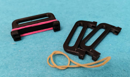
To remove the CM4 module from the ochin board, use the proper extractor. The .STL files for printing the extractor can be found in the “3D” section of the GitHub repository.
Power up the board with boot configuration as a “mass storage device”.
Power off the board (no Vin connected)
Press the “nRPiboot” button on the tiny external board and, keeping it pressed, power up the board using the “Vin” Connector.
Run the “RPiboot” software, downloaded from the Raspberry Pi . The PC will see the eMMC partition as if it were an SD card in the SD card reader.
Flash the eMMC using the OpenHD imageWriter.
The CSI camera can be connected to one of the two FFC connectors. The copper contacts of the flat cable must be oriented PCB-side.
The WiFi dongle can be connected to one of the 4 USB connectors on the board. It is advisable to cut a USB extender and solder it to a GHS connector, keeping the wires on the connector side as short as possible.
To connect the telemetry to the FC, use one of the available UART ports. The default UART is UART0 / 1. Ensure that the logic levels of the FC UART are 0V-3V3, as the GPIOs of the CM4 module are not 5V tolerant.
.
⚠️ This documentation is outdated! A current version is available at openhdfpv.org
Single Board Computers are little computer's like the Raspberry Pi, which are build to run computing tasks efficiently and without additional components. For the sake of simplicity we also include X86-Computers to that definition, even if they aren't sbc's at all.
Starting with the evo releases OpenHD managed the step to be less platform independend, which means that we not only support the RaspberryPi, but can be used on multiple platforms.
Currently OpenHD supports : X86,RPI,Rock5 and our Custom Hardware.
Our will allow the low latency features so many users requested, while also giving superb image quality and size.
Lowest latency can be achieved with OpenHD-Custom Hardware. Because of carefully selected SBC and Camera and a little "magic", which can't be reproduced on "normal" SBC's. This has the ability to cut the latency in half.
Second lowest latency can be archieved with Rock5, which can hardware encode in realtime h265.
For receiving lowest latency, currently the Rock5 or a X86 System with great performance is needed.
⚠️ This documentation is outdated! A current version is available at openhdfpv.org
Supported Raspberry's for the AirSBC in descending order from good to worse
Raspberry Pi Compute Module CM4
1,2
Earlier Raspberrys might work, but can't be officially supported anymore.
Requires a dt-blob.bin file for your carrier board when used as AIR to support dual cameras at the moment, ask for help in Telegram
Different carrier boards need different dt-blob.bin files, needs to be placed on the root of the SD-Card, if it differs from the ochin board-file
The most widely used and cost/effective
Supported Raspberry's for the GroundSBC in descending order from good to worse
Earlier Raspberrys might work, but can't be officially supported anymore.
Keep in mind, that your carrier board needs to support HDMI and needs (multiple) USB Ports to be used as Ground.
⚠️ This documentation is outdated! A current version is available at openhdfpv.org
OpenHD custom hardware is an ongoing project that is currently being developed and funded through https://www.patreon.com/OpenHD. The project aims to create a small and modular wireless high-definition video transmission system that is capable of transmitting and recording video in various resolutions and framerates with low latency capabilities.
The system is specifically designed to fit into the standard 30.5x30.5mm FPV drone stack system, making it easy to integrate into existing drone setups.
The project team is currently working on refining the design and improving its performance. The custom hardware system will be optimized to work with OpenHD and run specially created software.
It's worth noting that the OpenHD custom hardware project has already progressed beyond the conceptual stage and the team has developed several prototypes. These prototypes are currently being tested and refined.
If you would like to learn more about this project and stay up-to-date on its progress, be sure to visit . The team is always looking for new supporters and contributors to help bring this exciting project to life.
⚠️ This documentation is outdated! A current version is available at openhdfpv.org
X86 is a quite common Architecture. Most of modern Computers do run X86 processors, which often are much more powerfull then any SBC.
With 2.3-evo we start to support X86 in two ways.
We provide Images which are already setup and can be used via plugging an external USB-Drive/USB-Stick into your computer and run it live.
We provide X86 packages for Ubuntu 22.04. If you want you can build your own OpenHD Image/Setup right on your computer.
X86 will have different performance gains or losses depending on the Hardware used. The OpenHD Developers use quite potent Gaming-Hardware to test, so your experience will vary.
OpenHD will also interfere with your normal wifi-setup, it requires special drivers and may cause problems on your own installs.Thats why support always will be limited.
You can simply use our ImageWriter to flash OpenHD images to a USB-Stick. The Images can be found under the Advanced tab. (you do not need to setup ground or air, because it'll be selectable on the Desktop of the Image)
Please keep in mind, that your USB-Stick should be quite fast to reduce boot time.
When booted you'll be greeted by a Desktop which includes the Programs you need to run OpenHD. (You need to run OpenHD-Ground and QOpenHD for Ground usage)
Currently we only support Ubuntu 22.04 based Distributions.
Installing:
We added OpenHD as Standard Linux Application, so you can find it under Applications. Please select OpenHD-Air or OpenHD-Ground depending on your usecase. When running OpenHD as Ground, you also need to start QOpenHD to view the user interface.
** Wifi Adapter not found **
One cause could be that the drivers could not be installed because you are using secure boot
** Wifi Adapter (e.g. Asus AC56) does not show the indicator LED**
The new drivers don't support intercation with the LED anymore, so this is not a problem
⚠️ This documentation is outdated! A current version is available at openhdfpv.org
The ochin_CM4 board is a carrier board for the Raspberry Pi CM4 module and is meant to expose the connections to the peripherals made available by the CM4 module.
• 4x USB 2.0 480Mbps (4x SM04B-GHS-TB(LF)(SN) connectors)
• 1x USB Type-C (for flashing eMMC)
• 2x CSI camera (2x FH12-22S-0.5SH (55) connectors)
• I2C1 (SM04B-GHS-TB(LF)(SN) connector)
• SPI1 / 6 (SM06B-GHS-TB(LF)(SN) connector)
• UART0 / 1 + Video Out (SM06B-GHS-TB(LF)(SN) connector)
• UART3 / UART5 (SM06B-GHS-TB(LF)(SN) connector)
• USART4 (SM06B-GHS-TB(LF)(SN) connector)
The ochin_CM4 has no video output, it is designed to be used on the “air” side only.
The ochin_CM4 does not have a slot for the microSD, it is therefore mandatory to use Raspberry Pi CM4 modules with eMMC (not lite).
The Raspberry Pi CM4 module get pretty hot very quickly, please use an adequate heatsink.
The ochin_CM4 board is equipped with a 5VDC switching regulator, necessary to power the CM4 module and all the peripherals connected to it.
The regulator is able to accept input voltages from 7.5VDC to 28VDC (LiPo from 2S to 7S) and provide output currents up to 7A.
Thanks to the great power supplied by the regulator, it is possible to use the VBUS of the USB ports also to power the WiFi module, which is not normally recommended due to the large currents required by these modules.
However it should be noted that, to protect the CM4 module from any problems on the VBUS, the board is equipped with a current switch, which cuts the VBUS for currents higher than 3A.
This allows you to keep the CM4 module running even in the event of a short on the VBUS.
For this reason it is good to be sure to never exceed 3A on the VBUS (it is rare for a module to reach this limit, in fact 3A at 5V are 15W of power drawn).
However, it is possible to bypass the current switch in case you need more current on the VBUS, waiving the VBUS safety (see the ochin_CM4 board manual).
The CM4 connectors are quite delicate and very dense, so you need to be careful.
Before positioning the CM4 module, it is advisable to check that there are no specks of dust or other things that could prevent contact of the pins, if necessary clean with a brush and air.
Place the module gently on the connectors until you feel they are seated in each other (there is a first zero force step where they snap into). When you are sure that the two boards are perfectly aligned and the connectors engaged, press the two long edges of the CM4 module until the connectors are fully inserted.
It is advisable to limit the disassembly of the CM4 module as much as possible to avoid damaging the connector contacts.
To remove the CM4 module from the ochin board is always suggested to use the proper extractor.
You can find the .STL files to print .
The procedure to flash the CM4 eMMC it’s straightforward, what you need to do in synthesis is the following:
Power up the board with boot configuration as “mass storage device”. • To do so you need to power off the board (no Vin connected) • Press the “nRPiboot” button and, keeping it pressed power up the board using the “Vin” Connector. • Connect the board to your PC using the USB Type-C port
Run the “RPiboot” software, downloaded from the Raspberry Pi website. After the software starts, the PC will see the partition of the eMMC like if it would an SD into the SDcard reader.
Flash the eMMC using the OpenHD imageWriter.
OpenHd already includes the dt-blob.bin file, and 'dtoverlay=dwc2,dr_mode=host' has been enabled in 'boot/config.txt'.
The CSI camera can be connected to one of the two FFC connectors.
If you want to use the "Camera0" connector, make sure that the two jumpers of the I2C (used for the camera config) are shorted.
The WiFi dongle can be connected to one of the 4 USB connectors on the board.
In order to minimize the problems associated with connecting a "fast bus" such as USB, it is advisable to cut a USB extender and solder it to a GHS connector, leaving the wires on the connector side as short as possible.
To connect the telemetry to the FC it is possible to use one of the available UART ports, the UART used by default is UART0 / 1.
It is important to keep in mind that the GPIOs of the CM4 module are not 5V tolerant, it is therefore important to be sure that the logic levels of the FC UART are 0V-3V3.
Raspberry Pi 4B
Raspberry Pi 3B+
Raspberry Pi 3B
Raspberry Pi 3B mini
Raspberry Pi 3A
Raspberry Pi Compute Module CM3+
1
Raspberry Pi 2B v1.2
Raspberry Pi 3A+
Raspberry Pi Zero 2
3
Raspberry Pi Compute Module CM4
1
Raspberry Pi 4B
Raspberry Pi 3B+
Raspberry Pi 3B
Raspberry Pi Compute Module CM3+
1
sudo apt update && sudo apt upgrade -y && sudo apt install -y git && sudo git clone https://github.com/OpenHD/OpenHD-ImageBuilder && cd OpenHD-ImageBuilder && sudo ./X86-Installer.sh The CSI flat cable is very close to the USBs and is prone to RF noise. It’s suggested to shield the flat cable with copper tape (or at least alu tape).
The USB WiFi dongle will draw some Amps, please use supply cables of adequate size between the ochin_CM4 board and the USB dongle.
The ochin_CM4 cannot be powered via the USB-C connector. The Type-C connector is only used for writing the eMMC.
The CSI flat cable is very close to the USBs and it prone to RF noise. It’s suggested to shield the flat cable with copper tape (or at least alu tape);
The USB WiFi dongle will drawn some Amps, please use supply cables of adequate size between the ochin_CM4 board and the USB dongle.
⚠️ This documentation is outdated! A current version is available at openhdfpv.org
As OpenHD continues to evolve and introduce new features that require enhanced performance, we have made the decision to discontinue support for certain hardware that was previously compatible with earlier versions.
The following Single Board Computer (SBC) models are no longer supported:
⚠️ This documentation is outdated! A current version is available at openhdfpv.org
The Radxa Single Board Computers (SBCs) are highly capable devices that offer significantly higher performance compared to the Raspberry Pi. Due to their impressive capabilities, we have incorporated support for Radxa SBCs in our 2.4-Evo releases and newer.
However, it's important to note that the software development for Radxa SBCs is currently in its early stages. We recommend using them primarily on the ground where hardware decoding support is only partially functional. Despite this limitation, the performance is still superior to that of the Raspberry Pi.
At present, there is only one camera available for Radxa SBCs, namely the IMX415, which may not meet the requirements of OpenHD. To address this limitation, we are actively collaborating with Arducam to develop and offer better camera options for Radxa SBCs.
For it there is a initial pipeline included, but it may not function well. We're also working on a HDMI pipeline and the integration for this. But keep in mind that only the Rock5B does have this functionality.
In the near future, we have plans to introduce support for the newest camera module from Arducam, the IMX462.
The following Radxa SBC models are currently supported:
The following Radxa SBC models are currently being worked on:
*not technically radxa but we run radxa software on that board, it's also not the best working board, so it may take a lot of time until it is perfectly supported
Even 7 keys mapped to GPIO pins, only Right/Left/Up/Down needed for joystick navigation.
⚠️ This documentation is outdated! A current version is available at openhdfpv.org
The Jetson Nano is a capable H265 encoding device, that's why we supported it in our 2.2-evo till 2.3-evo releases. Since it is fundamently different and doesn't give any advantage on the Ground, we do not officially support it as GroundSBC.
Since Nvidia refused to update the Jetson SBC's at all and their software is totally outdated. We decided to discontinue Jetson Support. However experienced Developers can build and maintain their own Jetson images.
Previously Supported Jetson-SBC's
Raspberry Pi 1
Raspberry Pi CM1
Raspberry Pi Zero
Raspberry Pi Zero W
Jetson Nano 2GB
Jetson Nano 4GB
Jetson Nano 2GB
Jetson Nano 4GB
7
8
9
10
11
12
13
14
15
16
17
18
19
20
21
22
Del key
Backspace key
23
24
25
26
27
28
29
30
31
32
33
34
Right key
35
36
Enter key
Left key
37
38
Down key
39
40
Up key
Radxa Rock5B
Radxa Rock5A
Radxa CM3
Core3566*
Radxa Zero3W
1
2
3
4
5V INPUT
5
6
GNS